|
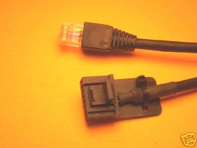
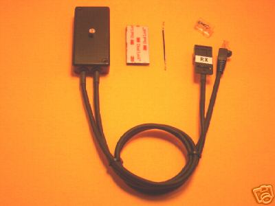
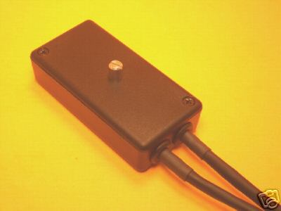
RA-1 REPEATER ADAPTOR FOR MOTOROLA RADIOS Fully assembled, plug & play unit Compatible with 5, 16 and 20-pin radios (see below) * Adjustable repeat audio level * 3-second dropout delay (can be shortened to 2, 1, or 0 seconds by internal jumper changes). * Compact unit measures 1.6 x 3.2 x .80". 22" radio cables. * Mounts securely with 3M Dual Lock fasteners, included. Introducing the RA-1 Repeater Adaptor. This handy device converts two Motorola mobile radios into a one-direction repeater. If you want to repeat signals in both directions (signals received on radio A are retransmitted by radio B and vice versa), please check out the RA-2, Bi-Directional Repeater Adaptor (click on MRE DIRECT, above). WHICH MOTOROLA RADIOS CAN THIS BE USED WITH? Radius, Maxtrac, GM300, SM120, CDM750, CDM1250, CDM1550. The transmit radio can be any of the above models, regardless of the rear accessory connector. All connections to the transmit radio are made via the front mic jack. Even older radios (with a 5-pin rear accessory connector) can be used as the transmitter. The receive radio must be either a 20-pin (CDM) model, OR is a 16-pin model with active-low carrier operated switch (COS) output on Pin 8 of the rear accessory connector. All 20-pin (and many 16-pin) radios already provide an active-low COS output on Pin 8, or are capable of being programmed to provide this output. Any two radios from the above list can be used, i.e.: two 16-pin Maxtracs, one 16-pin Maxtrac and a 5-pin Maxtrac, two CDMs, one GM300 and a CDM, etc. They do not have to be the same model as long as the receive radio provides a COS signal on Pin 8. A: You are equipped to program both radios, and: B: The radio to be used as the repeater receiver is either a 20-pin (CDM) model, OR is a 16-pin model that provides an active-low COS output on Pin 8 (please verify this, if necessary, by following the steps shown below before ordering). The accessory connector is fully programmable on all CDM radios. Any CDM model can be used as the receive radio (detailed programming instructions are included). Not all (but many) 16-pin radios can also be used as the receiver. Follow the steps shown below to verify your 16-pin receive radio is compatible. How can I verify my 16-pin receive radio has active-low COS output on Pin 8? 1. First, read the radio with RSS. Go to the Radio Wide Configuration screen (F2). Here, (if the radio has an expanded logic board), you will find a choice of F9. Press F9. This takes you to the Accessory Connector Configuration screen, where the definitions of pins 4,6,8,9,12 & 14 can be viewed or changed. Check to see if Pin 8 is already set as: (Description = PL/DPL & CSQ Detect; Data Direction = Output; Debounce = No; Active Level = Low). If yes, this radio can be used as the receiver for your repeater. If no, change Pin 8 to these parameters and write the change back to the radio. Now it can be used as the receiver. I have read my radio with RSS, but I do not see any option for changing the accessory connector (F9 does not appear on the Radio Wide Configuration screen). What now? 2. It might still be usable. On some 16-pin models, Pin 8 provides an active-low COS output, even though the accessory connector is not fully programmable. Check Pin 8 with a dc voltmeter (positive probe to Pin 8, negative probe to ground). Do you see approximately +5 volts on Pin 8 with the receiver squelched, and less than 0.1 volts when receiving a signal with the correct PL? If yes, this radio will work as the repeater receiver. No? Go to step 3. 3. Repeat the measurement from step 2, but this time, use a pull-up resistor to +12v (wrap one end of a 10k resistor around the positive voltmeter probe and connect the other end of the resistor to +12v). Reconnect the positive voltmeter probe to Pin 8. You should now see +12 volts on Pin 8 with the receiver squelched. Does this drop to less than 0.1 volts when receiving a signal with the correct PL? If yes, this radio will work as the repeater receiver. Where do I find Pin 8 on the accessory connector? I've measured the voltage on Pin 8 as described in steps 2 and 3, but I am not seeing an active-low transition when the radio unsquelches. What now? On some radios, even though the accessory connector is not fully programmable, Pin 8 can be made to provide an active-low COS output, by programming the radio in Repeater Mode (see step 4). 4. From the Main Menu, select F3 (GET/SAVE). Do you see an option of F6 (Change to Repeater Mode)? If so, try the following steps: Press F6 (Change to Repeater Mode). Press F2 (Read Repeater), and then press F10 for a Generic Repeater. Press F10 again to skip the transmit radio. Connect the programming cable to the receive radio and press F2 to read it. Keep pressing F2 until you reach the GET/SAVE menu. Then press F10, followed by F4. You will now be back at the CHANGE/VIEW menu, in Repeater Mode. Press F5 (Mode Configuration). Set the repeater type to Generic and enter your receive frequency and PL. There is only room to enter ONE (receive only) frequency & PL on this screen, but that's okay. Write this change back to the radio. This should cause Pin 8 to provide an active-low COS output (verify this with a voltmeter as described in steps 2 & 3 above). After you've programmed the radio in Repeater Mode (to get Pin 8 to behave as active-low COS), you can either leave it in Repeater Mode (if this radio will be dedicated solely to repeater receiver use), or you may return to the GET/SAVE menu and change it back to Radio Mode, which will allow you to program additional frequencies, if you wish. Pin 8 will remain set as active-low COS in either case. After first verifying active-low COS on Pin 8 of the receive radio as described above, plug the RX cable from the RA-1 into the 16 or 20-pin receive radio. On 16-pin radios, install the 2-inch jumper wire (included in the kit) between pins 15 & 16 of the RX plug, to enable the receive radio's internal speaker. On 20-pin (CDM) radios, the speaker jumper wire is not needed. Simply insert the RA-1's 16-pin RX plug into the radio's 20-pin jack, leaving 2 unused radio pins on either side of the plug. This configuration (16-pin plug inserted into a 20-pin jack) is perfectly okay. The 20-pin jack on the CDM radio is designed to accept either a 16 or 20-pin plug (a 20-pin plug is only needed for applications that use pins 17 thru 20). The 16-pin plug and 20-pin jack fit perfectly and are keyed (mistake-proof). They can only go together the correct way. The RA-1's transmit cable connects to the front mic jack of the transmit radio. A jumper plug (included) connects to the front mic jack of the receive radio to ground the mic hook switch, keeping the receiver in CTCSS mode. Use your RSS to enable the transmit radio's timeout timer and reduce the RF power level to approximately one-half of maximum. Position the transmit radio in a ventilated location and use a fan to provide plenty of airflow across the heat sink. Ensure that both radios are grounded to the same power supply. Connect a suitable antenna system - either two antennas with adequate physical separation, or one antenna and a properly tuned duplexer. Please click on "Store View" , above, to see other related items. (please look at our rules and privacy policy) |
M_cox@machine--tools.com (Miriam Cox) for additional information. This email is used for forwarding to newsgroup user.