|
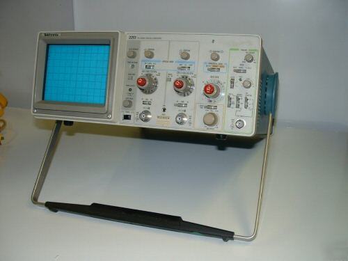
DPF_ENERGY is honest and reliable supplier of refurbished and adjusted testing instruments. Popular TEKTRONIX 2213 Analog Oscilloscope in excellent condition, without dents or scratches with full operator's and service manuals in pdf format (schematics, troubleshooting diagrams included) and probe. TEKTRONIX 2213 Oscilloscope is a dual trace 60MHz scope that combines performance, portability, simplicity, and proven reliability into one lightweight package (only 13.5 pounds). Designed to fulfill a wide range of applications, the 2213 can be found throughout the industrial, commercial, educational, and private sectors of the world. The 2213 can perform multiple tasks ranging from simple voltage measurements in the automotive industry, to repair of radios & televisions, to advanced troubleshooting and repairing of instruments in laboratories. This is a single time base oscilloscope with delayed sweep that features a bright, sharply defined trace on an 80x100 mm CRT. Even though the 2213 is one of the most simple-to-use scopes, it is also very powerful in its performance. Features include 2 mV sensitivity, advanced trigger system (including TV Field triggering), 5 nS/div sweep rate, and a very logically designed front panel. VERTICAL DEFLECTION (2 identical channels) Dc to 60 MHz, 20 mV/div to 10 V/div, 5.8 ns reduced Dc to 50 MHz, 2 mV to 10 mV/div 7 ns Dc to 50 MHz, 2 mV to 10 mV/div, 7 ns *2 At all deflection factors from 50Ω terminated source. 2 mV/div to 10 V/div ± 3% (+20°C to +30°C) or ± 4% (0°C to +50°C). 1-2-5 sequence. Uncalibrated, continuously variable between steps to at least 25 V/div. CH 1, CH 2, CH 2 Add (normal and inverted), Alternate, Chopped: approx. 250 kHz rate, electronically switched. At least 10:1 at 10 MHz for common-mode signals of 6 divisions or less. 1 MΩ Â± 2% paralleled by approx. 30 pF. 800 V (p-p ac at 1 kHz or less) 800 V (p-p ac at 1 kHz or less) Permits viewing leading edge of displayed waveform 0.05 µs/div to 0.5 s/div (1-2-5 sequence). 10X magnifier extends max sweep rate to 5 ns/div. Time Base A provides continuously variable uncalibrated sweep rates between steps to at least 1.25 s/div. A, A intensified after delay, delayed. < 0.5 µs, 10 µs, and 0.2 ms. Increases delay time by 20 to 1 or more. 5000 to 1 (0.02%) of maximum available delay time. Normal (sweep runs when triggered), automatic (sweep runs in the absence of a triggering signal and triggers automatically for signals down to 20 Hz), and TV field (with slope set for negative going transitions, and trigger level adjusted close to blanking level, sweep starts at first line of video; use Normal for TV line display). LED indicates when sweep is triggered. Adjustable control permits a stable presentation of repetitive complex waveforms. Auto and Normal Internal: Below 2 MHz, signal must be at least 0.4 div amplitude; requirements increase above 2 MHz; at 60 MHz, signal must be at least 1.5 div amplitude. Up to 2 MHz, trigger signal must be at least 50 mV p-p; requirements increase up to 60 MHz, where signal must be at least 250 mV p-p. Composite video must be at least 2 div amplitude. Internal: Trigger level can be adjusted over the range of amplitudes displayed on the CRT. External, Dc Coupled: Level can be adjusted over a range of at least ± 2 V, or 4 V p-p. External; Dc Coupled and Attenuated (divided by 10): Level can be adjusted over a range of at least ± 20 V, or 40 V p-p. R and C approx. 1 MΩ paralleled by approx. 30 pF. Separate slope and level controls for triggering B sweep. Up to 2 MHz, signal must be at least 0.4 div in vertical amplitude; requirements increase up to 60 MHz, where signal must be at least 2 div in amplitude. Full Sensitivity X-Y (CH1 Horizontal, CH 2 Vertical) 2 mV/div to 10 V/div accurate ± 5%. Bandwidth is dc to at least 2 MHz. Phase difference between amplifiers is 3° or less from dc to 50 kHz. 8 X 10 cm display. Horizontal and vertical center lines further marked in 0.2 cm increments. GH (P31) Phosphor standard. 10 kV accelerating potential, mesh grid, halo suppressed. Internal, non-parallax, not illuminated; markings for measurement of risetime. Compresses trace to within graticule area for ease in locating an off-screen signal. A preset intensity level provides a constant brightness. Dc coupled, positive-going signal decreases intensity; 5 V p-p signal causes noticeable modulation at normal intensity; dc to 5 MHz. Operating: 0°C to +50°C. Nonoperating: -55°C to +75°C. Operating: To 4600 m (15,000 ft); maximum allowable ambient temperature decreased by 1°C/1000 ft from 5000 to 15,000 ft. Nonoperating: 15,000 m (50,000 ft). Operating test samples were subjected to sinusoidal vibration in the X, Y and Z axis with the frequency varied from 10 Hz to 55 Hz to 10 Hz in 1 minute sweeps for a duration of 15 minutes per axis and a dwell of 10 minutes at 55 Hz. Total displacement was 0.015 in p-p (2.4 g's at 55 Hz). Operating and Nonoperating: Test samples were subjected to 5 cycles (120 hours) of humidity testing. Operating and Nonoperating: Test samples were subjected to 3 shocks, both directions along each axis for a total of 18 shocks. Peak accelerations of each 1/2-sine shock were 30 g's. Squarewave, 0.5 V ± 20%, 1 kHz ± 20%. 90 to 250 V, 48 to 440 Hz without range switching, 50 Ω maximum at 115 V and 60 Hz. Net (with cover accessories and pouch) Net (without cover accessories and pouch) One P6120 10X voltage probe;*1 One CP-260 1x-10x switchable probe;*1 Operator's manual, service manual See full Tek2213 spec on: /tek2213.html (please look at our rules and privacy policy) |
l.sykes@machine--tools.com (Lina Sykes) for additional information. This email is used for forwarding to newsgroup user.